
diff options
| author | krakenrf <78108016+krakenrf@users.noreply.github.com> | 2022-05-29 10:13:02 +0200 |
|---|---|---|
| committer | krakenrf <78108016+krakenrf@users.noreply.github.com> | 2022-05-29 10:13:02 +0200 |
| commit | 5d48846cb4c5cad97b241e386ae94e789f29b1a4 (patch) | |
| tree | f0aed69759d8d1b9fa121d7a34109ffee88efb87 | |
| parent | Created KrakenSDR Troubleshooting (markdown) (diff) | |
| download | krakensdr_docs.wiki-5d48846cb4c5cad97b241e386ae94e789f29b1a4.tar krakensdr_docs.wiki-5d48846cb4c5cad97b241e386ae94e789f29b1a4.tar.gz krakensdr_docs.wiki-5d48846cb4c5cad97b241e386ae94e789f29b1a4.tar.bz2 krakensdr_docs.wiki-5d48846cb4c5cad97b241e386ae94e789f29b1a4.tar.lz krakensdr_docs.wiki-5d48846cb4c5cad97b241e386ae94e789f29b1a4.tar.xz krakensdr_docs.wiki-5d48846cb4c5cad97b241e386ae94e789f29b1a4.tar.zst krakensdr_docs.wiki-5d48846cb4c5cad97b241e386ae94e789f29b1a4.zip | |
| -rw-r--r-- | KrakenSDR-Web-Interface-Controls.md | 316 |
1 files changed, 316 insertions, 0 deletions
diff --git a/KrakenSDR-Web-Interface-Controls.md b/KrakenSDR-Web-Interface-Controls.md new file mode 100644 index 0000000..12f7e28 --- /dev/null +++ b/KrakenSDR-Web-Interface-Controls.md @@ -0,0 +1,316 @@ +# Overview +The KrakenSDR GUI can be accessed through any network connected device via a web browser at http://IP_ADDR:8080 + +The GUI is used to start and stop the KrakenSDR data acquisition, and to control various parameters relating to direction finding, including the frequency, gain, and VFO channel settings. + +# Configuration Page + +## RF Receiver Configuration +**Centre Frequency** + +The frequency at the center of the active bandwidth. Changing this frequency and clicking update will trigger the noise source and start the coherence calibration procedure. + +**Receiver Gain** + +The universal gain setting for all five tuners. Check the SNR in the spectrum plot screen, and adjust the gain to achieve high SNR, and to avoid the spectrum overloading. + +> **NOTE: Any changes to the center frequency or receiver gain are only applied when the “Update Receiver Parameters” button is pressed.** + + +## DoA Configuration +<img src="https://user-images.githubusercontent.com/78108016/170477435-9876b424-0b5a-4c75-869d-dd52b564192d.png" width="400" align="right"/> +These settings need to be set for your particular antenna array setup and preferences. + +**Array Configuration** + +Choose what antenna array type you are using, either a linear “ULA” or circular “UCA” antenna configuration. + +**Antenna Radius/Interelement Spacing** + +Set the radius of the circular array, or the interelement spacing of a linear array here (in meters). + +**Wavelength Multiplier** + +(Non-Editable) Shows the spacing multiplier based on the frequency and array sizing. This should always be kept under 0.5, and ideally above 0.2. + +**Enable DoA Estimation** + +Enable computation of the direction-finding algorithms. + +**DoA Algorithm** + +Choose between various direction-finding algorithms. In almost all cases you will want to use the MUSIC algorithm. + +**Enable F-B Averaging** + +Forward-Backward Averaging. When you use a linear ULA array, this can be enabled and may improve multipath rejection. + +**ULA Output Direction** + +With a ULA array you will not be able to determine if a target is in front of, or behind the array. However, if you have prior knowledge and know the target is for sure either in front or behind the array, then you can truncate one direction using the settings here. + +**Array Offset** + +If the antenna array is oriented in a way that is not in-line with the vehicles axis of movement, then you can set the offset here. This is most useful for linear arrays that might be oriented along the front-back axis of a vehicle, as zero degrees for a linear array is orthogonal to the array. So in that case it would need to be rotated 90 degrees to be aligned with the vehicles axis of movement. + +## Display options +These options affect the DOA graph display. + +**DoA Graph Type** + +Changes between a linear, polar, or compass style plot for displaying DoA bearings. The linear and polar plots operate in the unit circle convention where 90 degrees is anticlockwise from 0 degrees. The compass plot operates in the compass/map convention where 90 degrees is clockwise. This may be changed in a future version, where only the compass/map convention is used, to avoid confusion. + +#### Compass Offset +If you use the compass plot, you can set a compass offset, to compensate for where your array is pointing. + +## VFO Configuration + +Configure properties relating to VFO handling. VFO's allow you to have multiple channels performing direction finding simultaneously within the active 2.4 MHz bandwidth. + +**Spectrum Calculation** + +Choose between `Single Ch` an `All Ch (TEST ONLY)`. + +Single channel mode only displays the RF from CH-1, but you must use this mode if you are using the squelch feature. + +All Ch mode is for testing and troubleshooting purposes only. It will display the spectrum graphs for all channels, but this is with significantly reduced time resolution. So it will easily miss short intermittent signals. + +**VFO Mode** +Choose between `Standard` and `VFO-0 Auto Max`. + +In standard mode the VFO's are controlled manually. e.g. you set a frequency for the VFO. + +In VFO-0 Auto Max mode, only VFO-0 is active, and it automatically tunes to the strongest signal in the spectrum. + +**Active VFOs** + +You can have up to 16 simultaneous VFO's. If necessary this can be increased beyond 16 - contact us if you have a need for more. + +Note about computation power: On a Pi 4 adding more than 3-4 VFO's that are on always active signals may slow down the processing enough so that channels with intermittent signals get missed. If you are not watching for short intermittent signals then this slow down will not matter significantly. + +If all channels are intermittent and properly squelched, then processing power should be sufficient as when channels are squelched they use no processing power. + +**Output VFO** + +You can choose between `ALL` or a single VFO. The ALL mode will output data for ALL active VFOs to the DOA Data Format. At the moment ALL only works with Kraken App, and the future Kraken Pro App. If you are using other DOA Data output formats, then you can choose a single VFO channel to output. + +**DSP Side Decimation** + +If you are looking at very narrowband signals over a small bandwidth, you can use decimation to reduce the full 2.4 MHz bandwidth to something smaller using decimation. A decimation factor of two will reduce the bandwidth by half to 1.2 MHz and so on. + +**Optimize Short Bursts** + +If you are squelching on weak, very narrowband CW signal bursts that have pulse periods less than about 50ms this option will help detect them better at the expensive of some computational power. + +## Station Information +This section is for settings specifically about the station and how the station outputs data. + +**Station ID** + +The name of this KrakenSDR station. Used to differentiate between multiple stations used in a network. + +**DOA Data Format** + +Sets the output data format. For example, the KrakenSDR Android App uses a different output format compared to DF Aggregator. Kraken App, Kerberos App and DF Aggregator output data to an HTML page at IP_ADDR:8081/DOA_value.html + +Kraken Pro Local and Remote outputs JSON data via a nodeJS websocket connection. + +RDF Mapper directly uploads to an RDF Mapper PHP API page. + +**Kraken Pro Key** + +If you are using our (still unfinished) Kraken Pro Remote system, enter your unique Key here. + +**RDF Mapper Server URL** + +If you are uploading to RDF Mapper enter the RDF mapper server address here. Don't forget to include the /save.php part at the end. + +**Location Source** + +If you have a gpsd compatible USB GPS device connected to your Pi 4, you can output this data in whatever DOA Data format you have chosen (if that format supports local GPS). A seperate GPS unit is not required if you're using the Kraken App, as Kraken App can make use of the smartphone GPS instead. + +**Latitude/Longitude/Heading** + +If you have selected your location source as 'Static', you can enter the latitude, longitude and antenna array heading for your stationary KrakenSDR station. + +## Local Data Recording +If you have no network connection, or no connection to a local Android device you can record DOA data directly to the SD card for later analysis. May be useful for example on a drone. + +Logs are written to the `~/krakensdr_doa/krakensdr_doa` folder. + +**Filename** + +Choose a unique filename for your CSV log file. + +**Data Format** + +The logging data format to be used. Currently only Kraken App is supported. This means you can open locally logged CSV files in the KrakenSDR Android App for mapping and triangulation analysis. + +**Write Interval** + +How often should data be written to the log file. The default of 1s is fine for a few hours of logging on a few channels. If you are logging for longer periods of time, and/or with many VFOs you may wish to increase this time to avoid the log file growing too large. + +With one VFO and a one second write interval, a log file will grow at a rate of about 100kB per minute. + +**Enable Local Data Recording** + +Turn on or off local logging. + +**File Size (MB)** + +Monitor this to ensure that the file size does not become huge. + +**Download File** + +Downloads the log file from the Web GUI. Note there is a bug with this button as it does not work in the server browser in the KrakenSDR Android App. Please open a standard Chrome browser on your Android device to download the file. + +## VFO Settings +For each VFO channel active there will be one VFO control box. Each box controls the individual VFO settings for Frequency, Bandwidth and Squelch. + +**Frequency** + +The frequency of the VFO channel. Must be within the 2.4 MHz bandwidth. See the Status box for the `VFO Range [MHz]` information which will show you the max and min possible frequencies. + +**Bandwidth** + +Set this to the expected bandwidth of the signal you are monitoring with this VFO channel. Bandwidth is specified in Hz. + +**Squelch** + +Set this to a value above the noise floor to activate the squelch feature. Squelching will ensure that DOA values are only output when there is an active signal. This will stop random DOA values from bring output when there is only noise and no signal, and will save on computation when no signal is active. + +The maximum squelch value is 0dB. + +# Spectrum Page +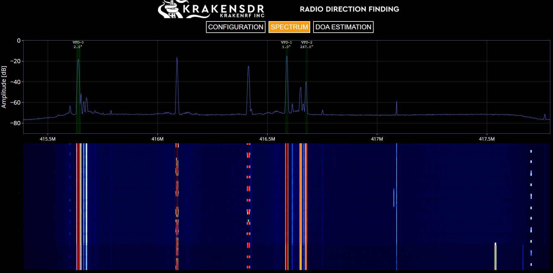 + +The spectrum page shows the live spectrum display and waterfall. + +It also shows the center frequency, bandwidth and squelch level for all VFOs that have been set. A VFO will display as green when the squelch threshold is reached, and red when it is not. + +## Click to tune +On the spectrum screen you select a VFO by clicking on the middle of it with the mouse. Once selected the border will thicken, indicating that this is the selected VFO. (Note that you may need to click more than once to register the click, unfortunately this is a bug with the current backend used) + +Now you can click anywhere on the spectrum or waterfall to move that VFO to a new frequency. + +# DOA Estimate Page +This page shows graphs of the DOA estimation. The graph is chosen by the `Display Options` configuration box on the configuration page. + +Please note that the Linear and Polar plots use the unit circle convention where 90 degrees is specified anticlockwise from 0 degrees. The compass plot uses the compass/mapping convention where 90 degrees is clockwise from 0 degrees. + +The DOA page is designed mostly for quick checks to see if the graph looks correct, but you can also use it for manual direction finding if required. The normal use-case is to display the bearing plots on a map via the Android App. + +# Additional DAQ Settings +The software is split into two parts. The Data Acquisition code (DAQ), and the Direction of Arrival Digital Signal Processing (DOA DSP) code. The DAQ settings can be changed via the GUI, but it is recommended to leave them alone unless you really know what you are doing. Below are some explanations for the DAQ settings which can be adjusted by clicking on `Basic DAQ Configuration` and `Advanced Custom DAQ Configuration`. + +## RF Receiver Configuration: Basic DAQ Settings +The DAQ setting can be controlled from the web interface too. However, we recommend that only advanced users change DAQ settings, even the basic DAQ settings. + +**Changes to the basic or advanced DAQ settings can be applied by pressing the “Reconfigure & Restart DAQ Chain” button.** This restart process may take a couple of minutes to complete. + +**Preconfigured DAQ Files** + +Choose a DAQ file configuration from a pre-set choice. Used mostly for switching between Kraken and legacy Kerberos settings. + +**Data Block Length** + +Integrated time of each processed block. Larger blocks provide more processing gain (higher SNR for weak signals), at the expense of slower update rates. The default of 436.9ms is optimal as it results in a power of 2 CPI size. + +**Recalibration Interval** + +How many minutes the system waits before checking up on coherence calibration and performing recalibration if calibration was lost for any reason. Under normal circumstances calibration should never be lost, but it’s a good idea to periodically check up on it anyway. + +## RF Receiver Configuration: Advanced Custom DAQ Configuration +These are advanced settings relating to the DAQ code. Unless you have a good reason to, these should not be adjusted under normal circumstances. + +**RX Channel** + +Set the number of RX channels to use for direction finding. Useful if you have a custom built system, or just want to experiment with less antennas in an array. + +If you are using a four channel KerberosSDR we recommend using the kerberos_default preconfiguration file instead of changing this directly. + +**Bias Tee Control** + +Enable or disable the 4.5V bias tee output on each channel. Only required if you need to power some sort of external device like an LNA. Enter as a comma delimited string. e.g. 1,0,0,0,0 would activate the bias tee on CH-0 only. 1,1,1,1,1 would activate the bias tee on all channels. + +**DAQ Buffer Size** + +The DAQ buffer size determines how big of a buffer the rtl_daq software collects before passing it on to the next stage. Under almost all conditions the default of 262144 works best. Setting it too large or too small could result in the rtl_daq thread being over or under worked. + +**Sample Rate** + +Set the hardware sample rate that the RTL-SDRs will be operating at. 2.4 MSPS is the widest supported. + +**Enable Noise Source Control** + +Allow the system to control the noise source for coherence calibration. Could be turned off if you are not using any coherence for any purpose. + +**CPI Size** + +Coherent Processing Interval. The rebuffer module will collect chunks of the DAQ buffer, and resize the output into the CPI Size. Larger CPI sizes result in longer acquisition times (larger data block length), but more processing gain. + +**Decimation Ratio** + +Control the DAQ side decimation. It may be useful to decimate on the DAQ side if you are sending raw coherent data over a network in order to reduce the size. + +**FIR Tap Size** + +The decimator is a FIR decimator. You can set the FIR tap size here. This needs to be bigger than the decimation ratio. + +**FIR Window** + +Set the FIR window type here. + +**Enable Filter Reset** + +Reset the memory of the FIR filter on every new CPI. + +** Correlation Size** + +The size of the block used for the calibration frames. Keeping this small ensures faster calibration, but having it too small with mean calibration could fail. + +**Standard Channel Index** + +The index of the channel that will be considered as the reference channel that all phase measurements will be made against. + +**Require Track Lock Intervention (For Kerberos)** + +Not fully implemented. The idea is that for old Kerberos units the software should pause on a recalibration for the user to be able to disconnect the antennas. + +**Calibration Track Mode** + +`No Tracking` needs to be used for older Kerberos units, as on every recalibration you need to manually disconnect the antennas on a Kerberos unit. +`Periodic Tracking` can be used with KrakenSDR units, or KerberosSDR units retrofitted with a switch. This will tell the software to periodically check on coherence calibration, just in case it has been lost (which is rare). A calibration check involves briefly turning on and switch to the noise source, so signal data within the few seconds it takes to check calibration will be lost. + +**Calibration Frame Interval** + +After how many frames should recalibration be checked. + +**Calibration Frame Burst Size** + +When we check calibration, how many frames should we check for. + +**Amplitude Tolerance** +During calibration to what amplitude difference should we tolerate. + +**Phase Tolerance** +During calibration to what phase difference should be tolerate. + +**Maximum Sync Fails** + +How many coherent calibration sync failures are required before recalibration is actually performed. + +**IQ Adjustment Source** + +This provides an option to calibrate the full system by compensating for phase differences in the antenna coax cables. + +`explicit-time-delay` - If you've measure time delay with a VNA you can input the differences here. Please note the differences must be measured relative to channel 0. TODO: Show how to calculate time delay from cable length + velocity factor. +`touchtone` - You can output .s1p files for the 5 coax cables in your system, and add them to the _calibration folder. Name them as cable_ch0.s1p, cable_ch1.s1p and so on. You need to ensure that the touchstone file covers the frequency range that you will be using. + +**IQ Adjust Amplitude** + +If you have some reason to manually adjust IQ amplitudes, this can be done here. + +**IQ Adjust Time Delay** + +If you are using `explicit-time-delay` as the IQ adjustment source, enter the delta phase differences here. (Relative to the CH0 cable, so delta = CH_0 - CH_X)
\ No newline at end of file |